
Steel bolts are an integral component of structural engineering, providing the strength and reliability needed to hold critical connections together in steel construction projects.
In Australia, the design, selection, and application of steel bolts are governed by stringent standards to ensure safety, durability, and performance across a wide range of industries, from construction to manufacturing. Many of these principles also align with international standards such as Eurocode EN 1993, supporting engineers working on cross-border or global projects.

This guide serves as a resource for engineers, architects, and construction professionals, offering clear insights into the key requirements and principles outlined in Australian Standards, including AS 4100 (Steel Structures) but is not a substitute for the standard itself, and all connections should be designed by a competent engineer in accordance with all jurisdictional requirements.
Let’s delve into the essentials of steel bolt design and how to apply these relevant standards effectively in your projects.
When to use a bolted connection
Bolted connections are commonly chosen over other structural steel connections (such as welded or riveted connections) in structural and mechanical applications for several reasons. Here are key situations where bolted connections are preferred:
Ease of assembly and disassembly
Bolted connections can be easily disassembled, making them ideal for temporary structures or components that require regular maintenance or replacement.
Additionally, prefabricated parts can be bolted together on-site, simplifying transport and reducing the need for on-site fabrication. Proper consideration should be given to the clearance around the bolt head and nut to ensure ease of assembly, especially in tight beam-column arrangements.
Field conditions
In field conditions where welding might be impractical due to weather, limited access, or lack of skilled labor, bolted connections are a more feasible option.
Bolting also avoids hazards associated with welding, such as fumes, fire risk, or the need for specialized equipment.
High-strength requirements
Bolted connections, especially with high-strength bolts (e.g., friction-grip or tensioned bolts), can provide excellent strength and stiffness, making them suitable for heavy structural applications.
Fatigue and dynamic loading
Bolted connections can perform better under dynamic or cyclic loads when designed correctly, as they allow some flexibility to absorb vibrations and stresses.
Material compatibility
Welding may not be suitable for dissimilar materials or materials prone to heat damage. Bolted connections avoid the thermal effects associated with welding.
Quality control and inspection
Bolted connections are easier to inspect for proper installation compared to welds, which may require advanced testing techniques (e.g., radiography or ultrasonic testing).
Cost-effectiveness
In many cases, bolting is more cost-effective than welding due to lower labor and equipment costs, especially for repetitive or large-scale connections. This is particularly true when using commercial bolts with coarse thread profiles, which are easier to handle and assemble.
Structural adjustments or expansion
Bolted connections allow for future modifications, such as expansions or retrofits, without significant disruption to the existing structure.
Common applications of bolted connections
- Bridge designs: For assembling large prefabricated sections.
- Industrial structures: Involving heavy equipment and dynamic loads.
- Temporary structures: Scaffolding, tents, or modular buildings.
- Mechanical assemblies: Machinery, vehicles, and other equipment requiring frequent maintenance.
Applicable Australian Standards for steel bolts
In Australia, the design, selection, manufacturing, and installation of steel bolts are governed by several key standards to ensure safety, performance, and compliance in structural and mechanical applications.
Below is an overview of the applicable standards by Standards Australia for steel bolts:
AS/NZS 1252: High-Strength Structural Bolting
- Part 1: Bolts, Nuts, and Washers: Covers the specifications for high-strength structural bolts, nuts, and washers used in friction-type and bearing-type connections. This includes typical commercial bolts with coarse thread configurations suited to structural use.
- Part 2: Verification Testing: Provides guidelines for testing procedures to verify the performance of high-strength bolts.
AS 4100: Steel Structures
- Provides comprehensive design rules for steel structures, including the design and use of bolted connections.
- Specifies requirements for bolt grades, spacing, edge distances, and load-carrying capacity.
AS/NZS 4680: Hot-Dip Galvanized (Zinc) Coatings on Fabricated Ferrous Articles
- Outlines the requirements for hot-dip galvanizing bolts and other steel components to enhance corrosion resistance.
AS/NZS 4291.1: Mechanical Properties of Fasteners
- Covers the mechanical properties of fasteners, including bolts, screws, and studs made of carbon steel and alloy steel. It specifies yield strength, tensile strength (in MPa), and minimum ductility to ensure safe deformation before failure.
AS/NZS ISO 898.1: Mechanical Properties of Fasteners Made of Carbon Steel and Alloy Steel
- Specifies mechanical properties for bolts, screws, and studs, including strength grades and testing methods. It also addresses thread types, such as coarse and fine threads, which influence the structural behavior and installation efficiency of bolts. It also addresses thread types, such as coarse and fine threads, which influence the structural behavior and installation efficiency of bolts. Property class 8.8 is most commonly referenced for structural applications due to its optimal tensile strength and proof load characteristics.
AS/NZS 1559: Hot-Dip Galvanized Steel Bolts with Associated Nuts and Washers for Tower Construction
- Specific to bolts used in tower construction, detailing requirements for galvanizing, dimensions, and mechanical properties.
AS/NZS 1214: Hot-Dip Galvanized Coatings on Threaded Fasteners
- Details the specifications for galvanizing threaded fasteners, ensuring proper coating thickness and quality.
AS/NZS ISO 3506: Fasteners Made of Stainless Steel
- Specifies the mechanical and physical properties of stainless steel bolts, screws, and nuts.
- Includes requirements for corrosion resistance and strength grades.
AS 1111: ISO Metric Hexagon Bolts and Screws
- Covers dimensions, tolerances, and specifications for ISO metric hexagon bolts and screws used in general applications.
AS 1112: ISO Metric Hexagon Nuts
- Specifies dimensions, tolerances, and technical requirements for ISO metric hexagon nuts used with bolts.
AS/NZS 1170.1: Structural Design Actions – Permanent, Imposed, and Other Actions
- Includes considerations for loads and forces that affect the design of bolted connections in structural applications.
This design guide will focus mainly on AS 4100: Steel Structures, which is the design guide used for engineers designing steel bolt connections. AS 4100 makes reference to the other standards above in its procedure, so it's important to have access to those standards as required.
Design of bolts
Bolting category
In AS 4100: Steel Structures, bolted connections are categorised based on the type of loading, the method of force transfer, and the performance characteristics of the bolts. These categories guide the design and application of bolts in structural steelwork.
The key bolt types in AS 4100 are:
Category 4.6/S and 8.8/S (Snug-Tightened Bolts)
Snug-tightened bolts are installed by bringing the connected plates into firm contact, without applying any deliberate pre-tension. This category includes bolts of property classes 4.6 and 8.8, with 4.6 offering lower strength and 8.8 providing higher tensile capacity.
These bolts are typically used in non-critical connections where slip resistance is not essential, such as secondary structural members, bracing systems, or temporary structures.
The load in these connections is primarily transferred through bearing between the bolt shank and the hole.
One of the main advantages of this category is its simplicity and cost-effectiveness—there is no need for special installation tools or procedures, making them ideal for general-purpose use.
Category 8.8/TB (Tensioned Bearing Bolts)
Tensioned bearing bolts, using high-strength bolts of property class 8.8, are installed by applying a specified minimum tension. Despite this pre-tensioning, the load transfer in the connection still relies mainly on bearing between the bolt shank and the hole.
These bolts are suited for structural connections subjected to higher loads, where the additional pre-tensioning enhances the connection’s robustness and resistance to loosening.
The advantage of this category lies in its increased load-carrying capacity compared to snug-tightened bolts, making it a reliable choice for higher-performance structural applications.
Category 8.8/TF (Tensioned Friction Bolts)
Tensioned friction bolts, also using property class 8.8 bolts, are installed with a specified minimum tension, but the force is transferred through friction developed between the connected surfaces.
This category is used in applications where preventing slip is crucial, such as in fatigue-sensitive structures or under dynamic loading conditions—typical examples include bridges, cranes, and connections experiencing cyclic or reversing loads.
Load transfer occurs via friction at the faying surfaces, and the effectiveness of the connection depends significantly on surface treatment to achieve the required slip factor.
Advantages include the elimination of slip under service loads and suitability for fatigue-prone conditions. However, to meet performance expectations, these connections require specific surface preparation, such as shot blasting or the use of special coatings.
Key differences between categories
Considerations for selecting bolting categories
When selecting a suitable bolting category, several factors must be considered:
- Static or dynamic loading determines whether friction or bearing is preferred.
- Use 8.8/TF for slip-critical connections.
- Snug-tightened bolts are simpler and cheaper but may not meet all performance needs.
- Friction connections (8.8/TF) require specific treatments to achieve adequate slip resistance.
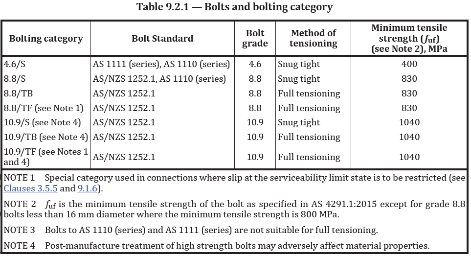
The bolts and bolting categories are listed in Table 9.2.1 of AS 4100 (2020) and must be designed in accordance with Clause 9.2 and Clause 9.3 of AS 4100.
Additionally, other property classes of bolts conforming to the AS 1110 series, AS 1111 series, and AS/NZS 1559 may also be designed using the provisions of these clauses.
Bolt strength limit states
To ensure the bolt has sufficient strength, AS 4100 uses the limit state method.
Bolt in shear
As per Clause 9.3 of AS 4100 (2020), a bolt subject to a design shear force (V*f) shall satisfy
$V^*_f\gt \phi V_f$
Where:
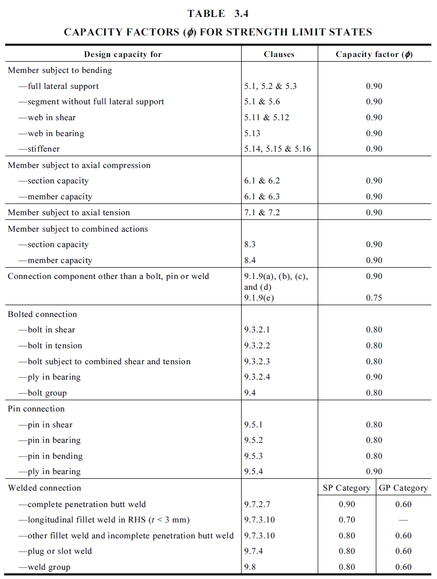
$\phi$ = capacity factor as per Table 3.4 AS4100(2020)
$V_f$ = nominal shear capacity of bolt = $0.62f_{uf}k_rk_{rd}(n_nA_c+n_xA_o)$
$f_{uf}$ = minimum tensile strength of the bolt as per Table 9.2.1 in AS4100(2020)
$k_{rd}$ = 0.83 for grade 10.9 bolts where threads intercept the shear plane,1.0 otherwise
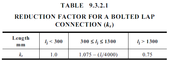
$k_r$ = 1.0 or for bolted lap connection reduction factor as per Table 9.3.2.1(2020)
$n_n$ = number of shear planes with threads intercepting the shear plane
$A_c$ = minor diameter area of the bolt as defined in AS 1275
$n_x$ = number of shear planes without threads intercepting the shear plane
$A_o$ = nominal plain shank area of the bolt
Bolt in tension
A bolt subject to a design tension force (N*tf) shall satisfy:
$N^*_{tf} \leq \phi N_{tf}$
Where:
$\phi$ = capacity factor as per Table 3.4 AS 4100 (2020)
$N_{tf}$ = nominal tensile capacity of a bolt = $A_sf_{uf}$
$A_s$ = tensile stress area of a bolt as specified in AS 1275
$f_{uf}$ = minimum tensile strength of the bolt as per Table 9.2.1 in AS 4100 (2020)
Bolt subject to combined shear and tension
A bolt required to resist both design shear (V*f) and design tensile forces (N*tf) at the same time shall satisfy:
$\left( \frac{V^*_{f}}{\phi V_{f}} \right)^2 + \left( \frac{N^*_{tf}}{\phi N_{tf}} \right)^2 \leq 1$
Ply in bearing
A ply subject to a design bearing force (V*b) due to a bolt in shear shall satisfy:
$V^*b \le V_b$
Where:
$\phi$ = capacity factor as per Table 3.4 AS4100(2020)
$V_b$ = nominal bearing capacity of a ply = 43.2d_ft_pf_{up}$
$V_b$ = min($3.2a_et_pf_{up}$)for a ply subject to a component of force acting towards an edge
$d_f$ =diameter of bolt
$t_p$ = thickness of the ply
$f_{up}$ = tensile strength of the ply
$a_e$ = minimum distance from the edge of a hole to the edge of a ply plus half the bolt diameter
Filler plates
As per AS4100(2020), connections in which filler plates exceed 6 mm in thickness but are less than 20 mm in thickness, the nominal shear capacity of a bolt (Vf) specified in Clause 9.3.2.1 shall be reduced by multiplying by [1 − 0.0154(t − 6)], where t is the total thickness of the filler, including any paint film, up to 20 mm.
AS4100(2020) also details that any filler plate shall extend beyond the connection and the extension of the filler plate shall be secured with enough bolts to distribute the calculated design force in the connected element over the combined cross-section of the connected element and filler plate. For multi-shear plane connections with more than one filler plate through which a bolt passes, the reduction shall be determined using the maximum thickness of filler plate on any shear plane through which the bolt passes.
Bolt serviceability limit state
Bolt in shear
For friction-type connections (bolting category 8.8/TF) in which slip in the serviceability limit state is required to be limited, a bolt subjected only to a design shear force (V*sf) in the plane of the interfaces shall satisfy
$V^*_{sf} \le \phi V_{sf}$
Where:
$\phi$ = capacity factor as per Clause 3.55 AS4100(2020) =0.7
$V_{sf}$ = nominal shear capacity of a bolt for a friction type connection = $\mu n_{ei}N_{ti}k_h$
$\mu$ = slip factor as specified in Clause 9.2.3.2 of AS4100=0.35 unless other test result provided
$n_{ei}$ = number of effective interfaces
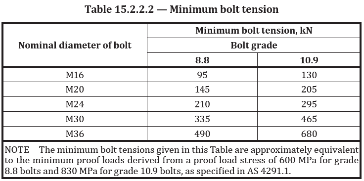
$N_{ti}$ = minimum bolt tension at installation as specified in Clause 15.2.2.2 of AS4100(2020)
$k_h$ = 1.0 for standard holes, 0.85 for short slotted or oversize holes, 0.7 for long slotted holes
Bolt subject to combined shear and tension
As per Clause 9.2.3.3 in AS4100(2020) bolts in a connection for which slip in the serviceability limit state shall be limited, which are subject to a design tension force (Ntf), shall satisfy
$(\frac{V^*_{sf}}{\phi V_{sf}})^2+(\frac{N^*_{tf}}{\phi N_{tf}})^2\le 1$
Where:
$N_{tf} = N_{ti}$
Assessment of the strength of a bolt group
In plane loading
As per Clause 9.3.1 in AS4100(2020), each bolt shall satisfy the requirements of Clause 9.2.2.1 of AS4100(2020) and the ply in bearing shall satisfy Clause 9.2.2.4 of AS4100(2020).
Out of plane loading
As per Clause 9.3.2 in AS4100(2020), the design actions in any bolt in a bolt group subject to out-of-plane loading shall be determined in accordance with Clause 9.1.3 of AS4100(2020). Each bolt shall conform to Clauses 9.2.2.1, 9.2.2.2 and 9.2.2.3 of AS4100(2020) and the ply in bearing shall satisfy Clause 9.2.2.4 of AS4100(2020).
Bolt Subject to In Plane and Out of Plane Loading
As per Clause 9.3.1 & 9.3.2 in AS4100(2020), the design actions in any bolt in a bolt group subject to out-of-plane loading shall be determined in accordance with Clause 9.1.3 of AS4100(2020). Each bolt shall conform to Clauses 9.2.2.1, 9.2.2.2 and 9.2.2.3 of AS4100(2020) and the ply in bearing shall satisfy Clause 9.2.2.4 of AS4100(2020).
Design procedure for bolts
The following steps summarise the design procedure for bolted connections under AS 4100. These high-level steps serve as a practical checklist, with detailed calculations and application examples provided in the subsequent section.
- Determine nature of loading (in plane, out of plane, combined in plane and out of plane)
- Determine type of load action on bolts (shear, tension, combined shear and tension)
- Calculate load action
- Calculate shear and tension design capacities
- Determine if strength limit state is satisfied
- Determine if serviceability limit state is satisfied
Bolt design by hand calculation
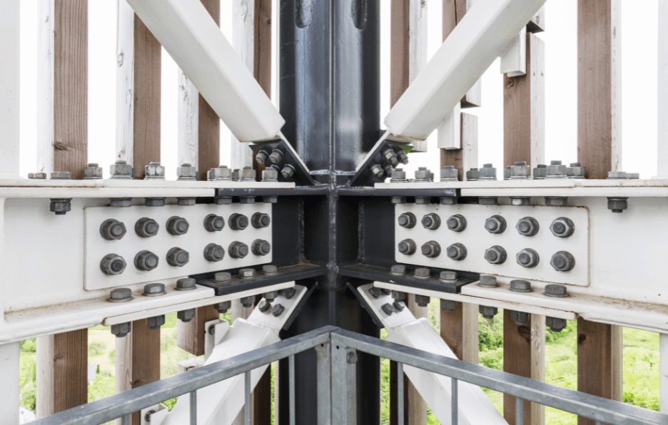
An end plate is welded to the end of a universal beam that is to be bolted to the flange of a universal column to form a beam-column connection. The builder wants to use a 2 x 2 bolt M12 8.8/S bolt arrangement. The end plate is 370mm x 150mm to fit onto the flange of the column and is 12mm thick with 440MPa tensile strength. The welded end plate connection is exerting a shear force of 80kN on the bolt group as well as a 20kNm out of plane moment.
Hand calculation for bolt in shear
A bolt subject to a design shear force (V*f) shall satisfy
$V^*_f\gt \phi V_f$
$V^*_f= \frac{\text{force on bolt group}}{\text{number of bolts}}=\frac{80kN}{4} = 20000N$
$ \phi V_f$ = 0.62$f_{uf}k_rk_{rd}(n_nA_c+n_xA_o)$ = 0.62 * 830 * 1.0 * 1.0 * (1*113.04) = 58,170$N$
Therefore, $V^*_f\gt \phi V_f$ is safe for shear.
Where:
$\phi$ = 0.8 capacity factor for bolt in combined shear and tension as per Table 3.4 AS4100(2020)
$V_f$ = nominal shear capacity of bolt= $0.62f_{uf}k_rk_rd}(n_nA_c+n_xA_o) = 0.62 * 830 * 1.0 * 1.0 * (1*113.04)
$f_uf$ = 830MPa minimum tensile strength of the 8.8/S bolt as per Table 9.2.1 in AS4100(2020)
$k_{rd}$ = 1.0 (not a high grade 10.9 bolt)
$k_r$ = 1.0 (not a bolted lap connection)
$n_n$ = 1 = number of shear planes with threads intercepting the shear plane
$A_c$ = minor diameter area of the bolt as defined in AS 1275 = $\pi r^2$ = $\pi 6^2$ = 113.04mm2
$n_x$ =0 = number of shear planes without threads intercepting the shear plane
$A_o$ = nominal plain shank area of the bolt = $\pi r^2$ = $\pi 6^2$ = 113.04mm2
Hand Calculation for bolt in tension
There is a 20kNm out of plane moment exerted on the connection which causes a tensile force on the top two bolts and a compressive force on the bottom two bolts of the 2 x 2 bolt arrangement. This tensile value is calculated using stress equations to determine the axial loads on the bolts, caused by the out-of-plane moment.
Tensile Force $N = \sigma A$
$N=\frac{M_x(y_i)}{Ix}A=\frac{20,000,000*(150)}{90,000}*1=33,333N$
Where:
$M_x$ = 20kNm = 20,000,000Nmm
eccentricity ($y_i$) = 150mm (distance from centroid to bolt group)
$I_x$ = moment of inertia for bolt group = $\sum_{}^{}(y_i^2)$ =1502(bolt 1) +1502(bolt 2) +1502(bolt 3)+1502(bolt 4) = 90,000mm2
Therefore there is a 33.3kN tensile force on each bolt in the top row and a 33.3kN compressive force on each bolt in the bottom row due to the out of plane moment applied to the beam.
A bolt subject to a design tension force (N*tf) shall satisfy:
$N^*_{tf} \leq \phi N_{tf}$
$N^*_{tf} = \frac{\text{force on bolt group}}{\text{number of bolts}} = \frac{33.3kN}{2} = 16650N$
$\phi N_{tf}$ =$\phi A_sf_{uf}$ = 0.8 * 56.51 * 830 = 37522N
Therefore, $N^*_{tf} \leq \phi N_{tf}$, and the bolt is safe for tension.
Where:
$\phi$ = 0.8 as per capacity factor as per Table 3.4 AS4100(2020)
$N_{tf}$ = nominal tensile capacity of a bolt = $A_sf_{uf}$
$A_s$ = $\frac{\pi r^2}{2}$ = $\frac{\pi 6^2}{2}$ = 56.51mm2 tensile stress area of a bolt as specified in AS 1275
$f_{uf}$ = 830MPa = minimum tensile strength of the bolt as per Table 9.2.1 in AS4100(2020)
Hand calculation for bolt subject to combined shear and tension
A bolt required to resist both design shear (V*f) and design tensile forces (N*tf) at the same time shall satisfy:
$(\frac{V^*_f}{\phi Vf})^2+(\frac{N^*_{tf}}{\phi Ntf})^2\le 1$
$(\frac{20000}{58170})^2+(\frac{16650}{37522})^2\le 1$
$0.31\le1$
Therefore, the proposed bolt design is safe.
Hand calculation for ply (plate) in bearing
A ply subject to a design bearing force (V*b) due to a bolt in shear shall satisfy:
$V^*_b\le V_b$
The design action is 33.3kN of bearing force on the plate
33,300N$\le$ $\phi min(3.2a_et_pf_{up},3.2d_ft_pf_{up})$ = 0.9(3.2 * 12 * 12 * 440,3.2 * 35 * 12 * 440) = 182,475N
Where:
$\phi$ = 0.9 capacity factor for ply in bearing as per Table 3.4 AS4100(2020)
$V_b$ = nominal bearing capacity of a ply = $3.2d_ft_pf_{up}$
$V_b$ = $\phi min(3.2a_et_pf_{up},3.2d_ft_pf_{up})$ for a ply subject to a component of force acting towards an edge
$d_f$ = diameter of bolt = 12mm
$t_p$ = thickness of the ply = 12mm
$f_{up}$ = tensile strength of the ply = 440MPa
$a_e$ = 35mm min distance from the edge of a hole to the edge of a ply plus half the bolt diameter
Therefore, the proposed plate design is safe.
Bolt serviceability limit state
Not required to be checked as this check is only performed for friction-type connections (bolting category 8.8/TF.
Bolt design with ClearCalcs
Let’s perform the previous example completed by hand calculation with ClearCalcs. A reminder of the problem below.
An end plate is welded to the end of a universal beam that is to be bolted to the flange of a universal column to form a beam-column connection. The builder wants to use a 2 x 2 bolt M12 8.8/S bolt arrangement. The end plate is 370mm x 150mm to fit onto the flange of the column and is 12mm thick with 440MPa tensile strength. The welded end plate connection is exerting a shear force of 80kN on the bolt group as well as a 20kNm out of plane moment.
Input the ultimate loads and bolt arrangement
The first step in the connection design is to input the ultimate loads exerted on the bolt group which are known from the problem. If you are struggling to determine the loads acting on your connection, refer to our article on Load and Tributary Width which offers guidance on the design process. For this example, we can input a shear force of -80kN (negative as the force is down from the beam) and the out of plane moment of 20kNm.

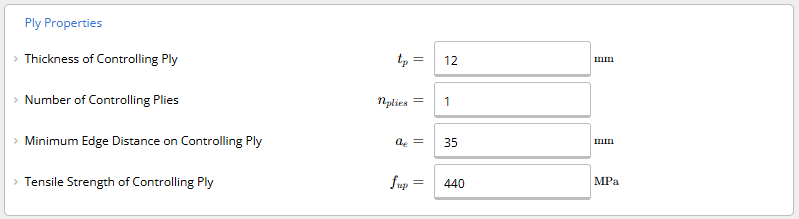
Input the ply properties
The next step is to input the ply properties. In this case, the builder has requested to use 12mm thick plate that is 440MPa. Let’s specify 35mm as the minimum edge distance on the plate. We would recommend a min edge distance of 30mm.
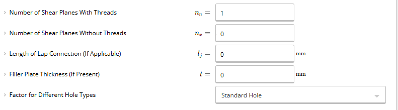
Input the known key properties
The known key properties are then populated, with the number of shear planes with threads set to 1 and we will specify standard holes. There are no shear planes without threads, no lap connections and no filler plate thickness for this problem and most standard designs.
Specify bolt size and arrangement
Let’s now design the bolt arrangement. The bolt assembilies must consider the dimensions of the end plate (called ply in AS4100 (2020)) which is determined by the flange dimensions of the column or vertical member that the beam is being fixed to. If the flange width is say 150mm, then the width of the plate (ply) must be equal or less than that. We must also factor in the minimum edge distance on controlling ply (ae) which we have specified as 35mm in the previous step.
x bolt offset (mm) = $\frac{\text{width of controlling ply} - (2^*a_e)}{\text{number of bolts in top row}} = \frac{150 - (235)}{2} = 40mm$
y bolt offset (mm) = $\frac{\text{width of controlling ply}-(2^*_{ae})}{\text{number of bolts in top row}}=\frac{370 - (2*35)}{2}=150m$
We can specify these bolt locations as per the below table, with bolt 1 being top left, bolt 2 being bottom right, bolt 3 being bottom left, and bolt 4 being top right, as per standard sign conventions.
One of the best features of using the ClearCalcs Steel Bolt Calculator to AS4100 is that the calculator automatically distributes the total load on the connection to each of the bolts based on the locations you specify, this saves substantial time on computing the tensile/compressive forces on each load based on moments applied to the connection which is typically done by hand and has to be repeated every time a new bolt arrangement is trialled.
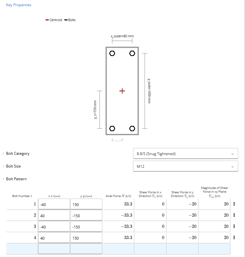
The next step is to specify the bolt size and design the bolt arrangement. Given the builder has proposed to use M12 bolts we will specify those with the category as 8.8 snug tightened (which is the most common grade and fixing method.
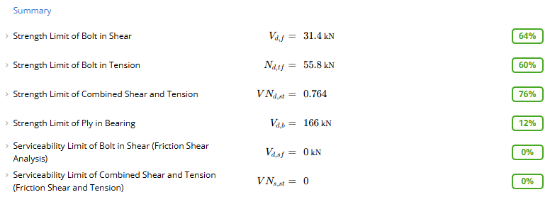
Assess load utilisation
ClearCalcs provides instant load utilisation results as soon as any parameter is changed, which means we can find the most efficient design rapidly, with instant feedback on how each parameter affects the strength and serviceability of the bolt design.
As we can see in the below example, the M12 8.8/S bolts are satisfactory. But if they weren’t, we could increase the size or grade of the bolts or adjust the bolt arrangement in the previous step by increasing the eccentricity of the x and y offsets to reduce the tensile forces on the bolts arising from applied moments or increase the number of bolts in the arrangement. ClearCalcs Steel Bolt Calculator to AS4100 provides instant feedback on these changes so that there is no need to waste time repeating all the calculations outlined in the hand calculation example again and again to achieve compliance and safety.
Conclusion
Steel bolts are a fundamental element in structural engineering, and designing them in compliance with Australian Standards ensures safety, durability, and performance in every project.
By understanding the key standards, bolting categories, and design principles outlined in this guide, engineers and construction professionals can make informed decisions that lead to efficient and reliable connections.
For faster, more accurate and more structurally efficient bolt design calculations, we recommend using ClearCalcs Steel Bolt Calculator to AS4100. This intuitive platform simplifies compliance with Australian Standards, enhances productivity, and ensures precision in your designs.
Whether you’re working on a simple project or a complex structure, ClearCalcs can help you achieve the best outcomes with confidence.
Sign up for a free trial today.
Further resources
For engineers seeking to deepen their understanding or stay current with evolving standards and best practices, the following resources are highly recommended:
Australian Steel Institute (ASI)
The ASI offers a wealth of technical resources, training programs, and design guides. Key resources include:
ASI Design Guide 1: Bolted Connections
This comprehensive manual expands on bolted connection theory and application in real-world scenarios.
Standards Australia
Standards Australia is the body responsible for developing and maintaining the AS/NZS series. To access or purchase official documents:
AS 4100:2020 – Steel Structures
The definitive guide for structural steel design in Australia, including bolted and welded connection requirements.
ClearCalcs
Steel Bolt Calculator to AS 4100
Streamline design and code compliance with ClearCalcs' calculator—ideal for Australian structural engineers working on residential or industrial steel projects.
Hollowcore - Anchorage and Seismic Retrofit
September 23rd at 10 am New Zealand Time (NZT)
Save your spot →Written by:

Kyle Conway
.svg)
Reviewed by:


.png)
